
5. Physics and Raycasting-1
Physics in Unreal Engine is responsible for the simulation and collision of all physical actors, which means any motion, like falling or applying a force or interaction between them is done using physics. At the time of this book was written, Unreal used PhysX version 3.4, which was used for all simulations.
UE4 includes a built-in high-performance custom physics engine called Chaos Physics Engine, which (at the time of writing this book) is only available through the GitHub source. Chaos Physics is expected to be production-ready in UE4 version 4.26.
Raycasting (also known as trace) is the process of sending an invisible ray from one location to another location in the game world and determining if the ray hit anything. The hit result contains information that you can use to alter the game state.
In this chapter, you learn about Simulation, Collision, and Trace.
Simulation
When an object is falling or moved by applying some force, then that object is simulating physics. For physics to simulate, the mesh must have a collision shape first. Because the actual 3D mesh can be complicated, UE4 uses simple proxy shapes, which are called Physics Bodies (also known as BodyInstances), such as a box, sphere, capsule, or custom convex hull to simulate physics. The properties for this physical body are adjusted by selecting the mesh on which you want to apply physics. For example, in Chapter 3, we assigned a Static Mesh Component and created a Blueprint class for our C++ actor.
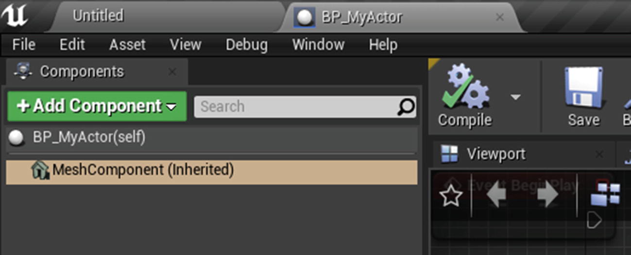
- 1.Open the Blueprint and select MeshComponent (Inherited) from the Components tab (see Figure 5-1).
- 2.In the Details panel, scroll down to the Physics category (see Figure 5-2).
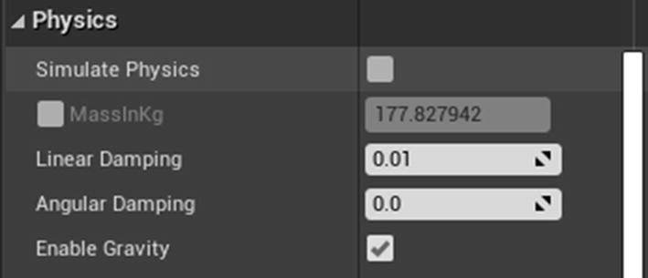
Let’s look at these properties.
- Simulate Physics: Enables or disables physics simulation. If this option is grayed-out, you don’t have a collision set up on the selected mesh. For Skeletal Mesh, you need a physics asset setup, and for Static Mesh, you need a simple collision setup.
- MassInKg: The mass of the object in kilograms.
- Linear Damping: The drag force applied to a linear movement, which determines the movement in a straight line.
- Angular Damping: The drag force applied to an angular movement, which is the rotational equivalent of linear movement.
- Enable Gravity: Determines if the physics simulation should have the force of gravity applied.
Collision
In Unreal, every object with Collision is assigned an object type, which defines how it interacts with other object types. Some object types can block, some can overlap, and others can ignore. An object can also define how it should react to traces using trace channels. By default, there are two types of trace channels: Visibility and Camera.There are two types of collisions: Blocking and Overlaps.
- Blocking collisions occurs when two objects collide and cannot pass through (e.g., an object hitting a wall).
- Overlap collisions occur when two objects overlap each other (e.g., an object falling into water).
Collisions are determined by the preset on the component under the Collision category. Collisions generate events with information, including with whom the collision occurred. Figure 5-3 shows the Collision properties.
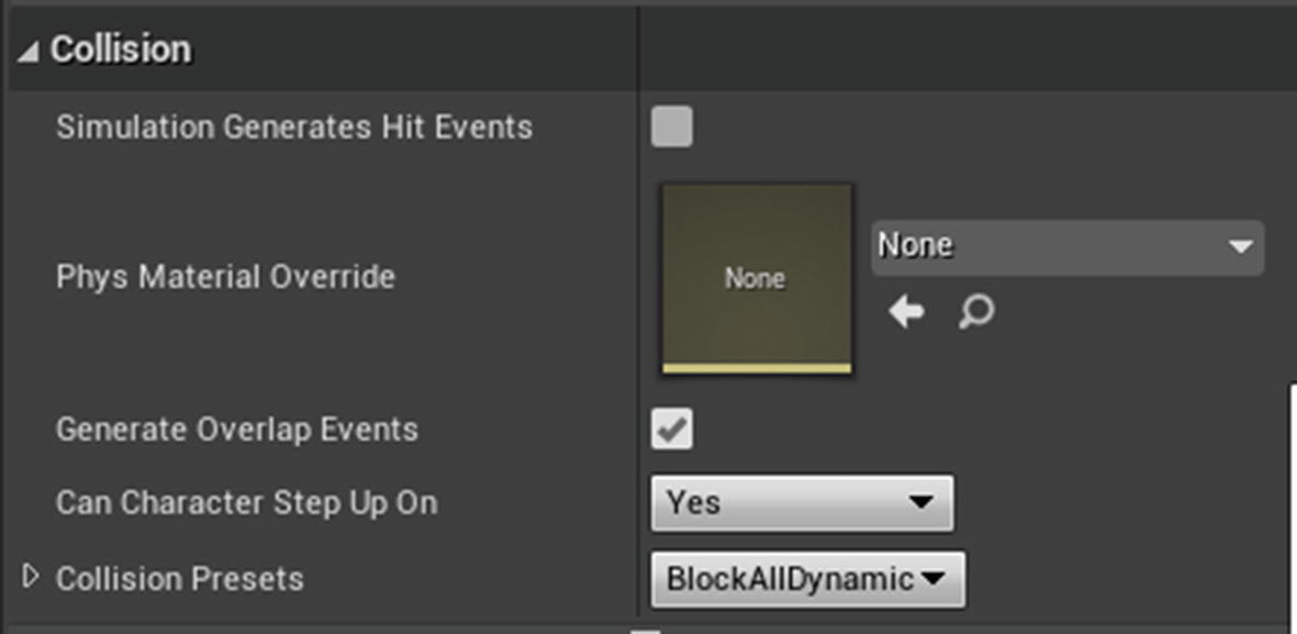
- Simulation Generates Hit Events: If true, this physics body calls a native On Component Hit event when a collision is a success.
- Phys Material Override: Assign a physics material (not to be confused with the material in the next chapter) to define properties such as Friction, Restitution, and Density.
- Generate Overlap Events: If true, this physics body calls a native On Begin Overlap event when the overlap starts and calls an On End Overlap event when overlapping ends.
- Can Character Step Up On: Determines if the player character can step onto this object. If No, the player is rejected if they try to step on it.
Collision has four different states.
- No Collision: There is no representation for any type of collision. This means no overlapping or blocking.
- Query only: The object can only trigger overlap events, and no rigid body collisions; the object cannot block any other objects.
- Physics only: The object can interact with other objects but does not support overlaps.
- Collision enabled: The object can overlap and block other objects.
Let’s now look at defining a new trace type and using it in the game to pick up an item.
Using Trace (Raycast) to Pick up an Item
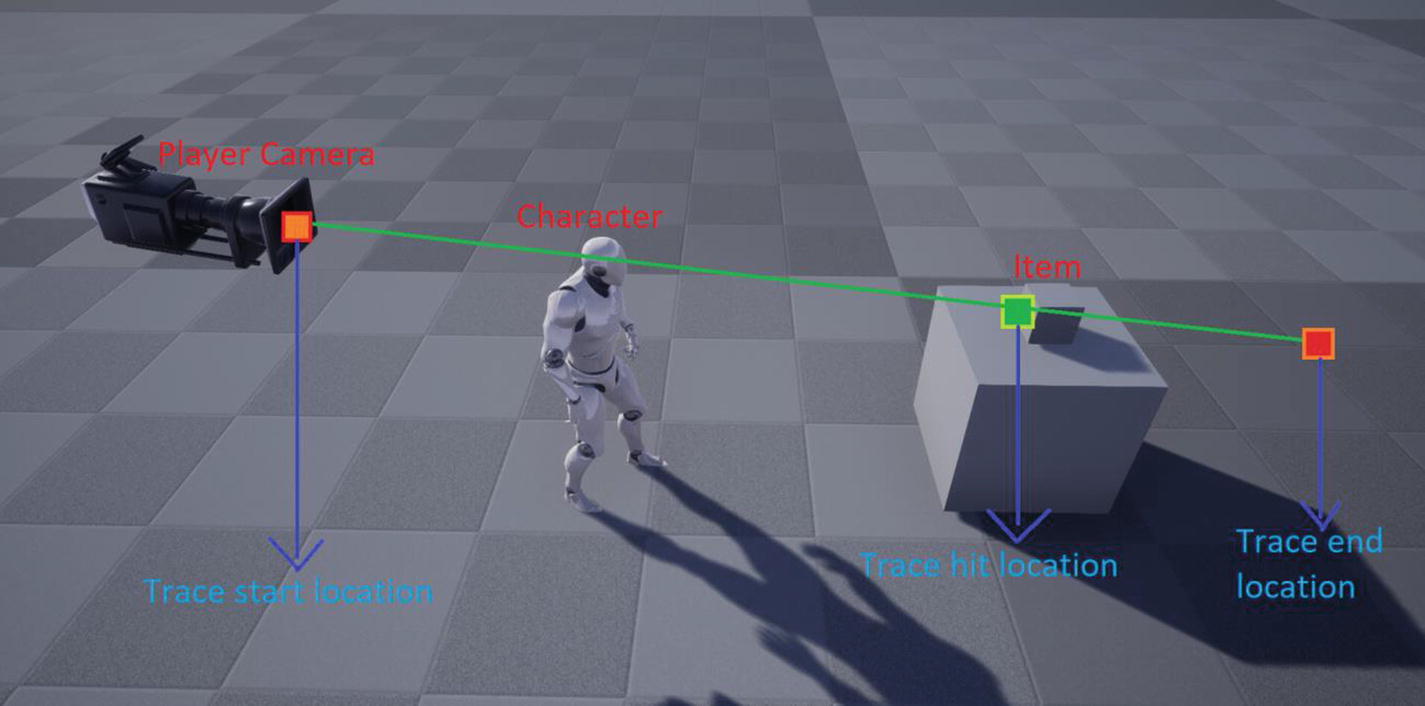
When you want to pick up an item in a game, you look at the item first and press a specific key. When you press that key, under the hood, the Engine sends an invisible ray from the camera location with a specified length. In between the start location and the end location, if the trace hits an object, it returns a hit result containing hit information. Figure 5-4 illustrates how trace works.
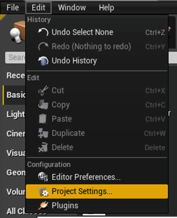
So how does the trace know what to hit? It is done using a trace channel. Unreal Engine comes with two trace channels: Visibility and Camera. In this section, you create our own trace channel, set it to an item, and use trace to detect it.First and foremost, let’s create a trace channel. Open Project Settings by clicking Edit on the menu bar, and then select Project Settings (see Figure 5-5).
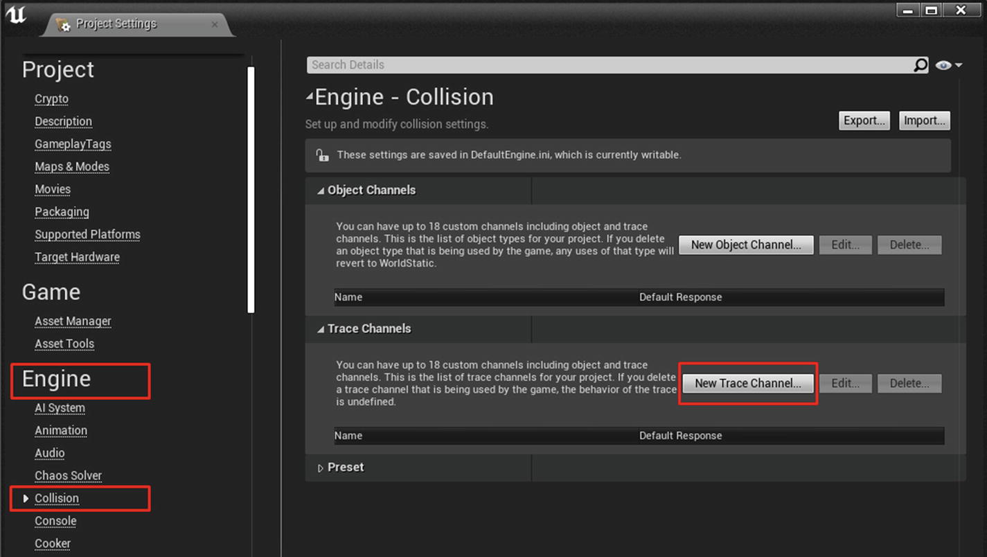
From the Project Settings, click Collision under the Engine section to modify the collision settings (see Figure 5-6).
Click the New Trace Channel button under the Trace Channels category. A new dialog box appears, prompting you to name the trace and a default response. Enter the name as MyItemTrace and set the default response to ignore (see Figure 5-7).
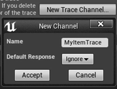
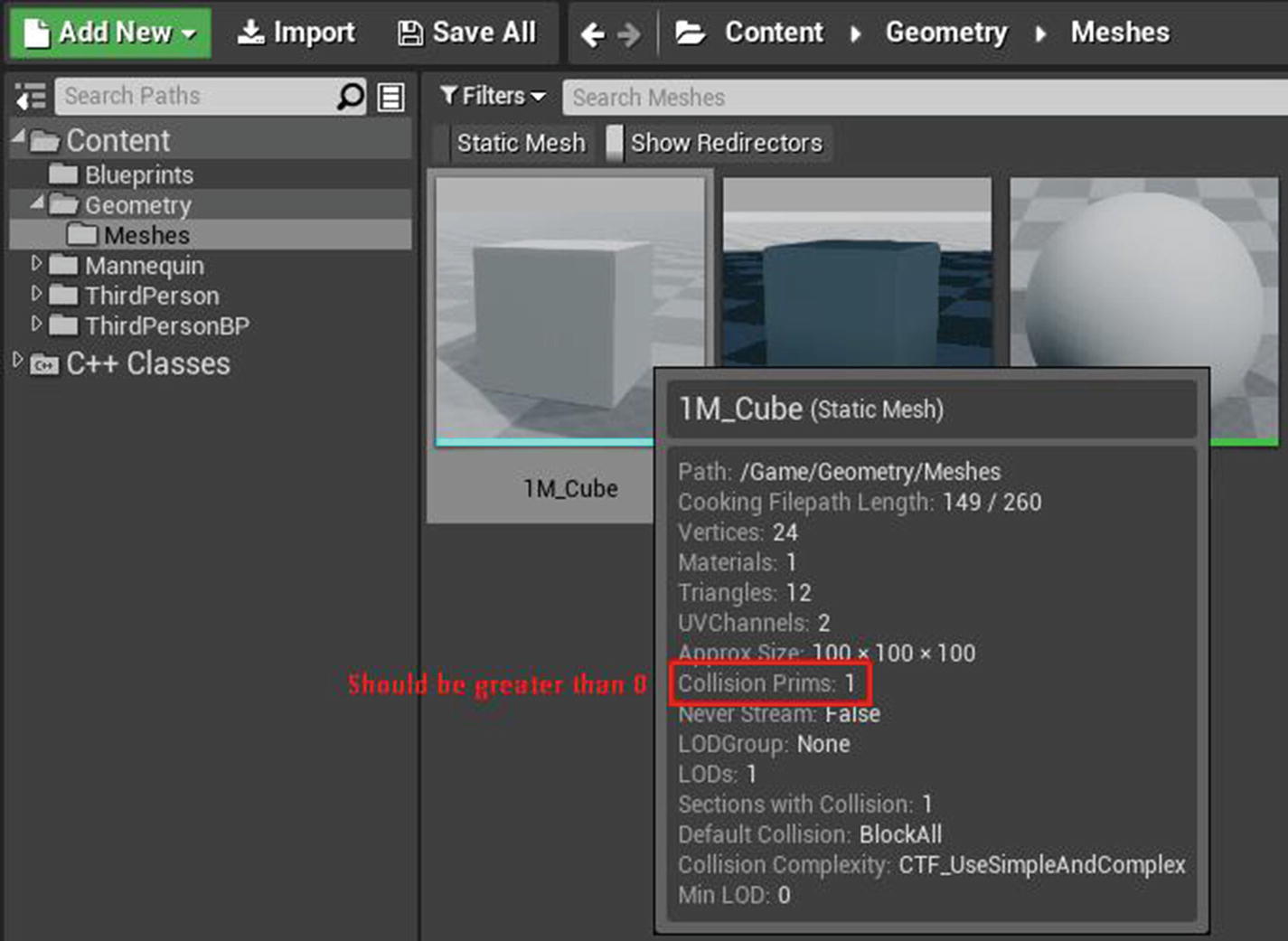
After pressing the Accept button, you see your newly created trace under the Trace Channels category. You can now access this trace channel under every mesh component to enable or disable it.Before we do anything else, let’s first make sure the mesh you are using (1M_Cube) has collision available. Go to the Content Browser where the mesh is located, and hover your mouse over the mesh. In the tooltip, if the Collision Prims is greater than 0, then the mesh has collision included (see Figure 5-8).
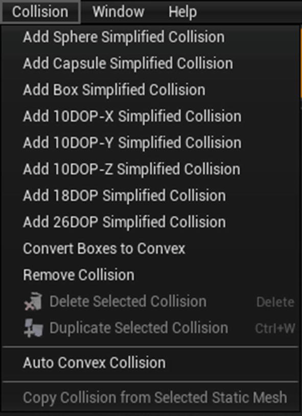
If the mesh is a missing collision, you can generate a collision shape inside the Static Mesh Editor. From the menu bar, click Collision and select an option to generate your desired collision shape. For simple shapes, you can choose box, cylinder, sphere, or so forth, but for complex shapes, select Auto Convex Collision (see Figure 5-9).
To use the trace channel, you first open your previously created Blueprint Actor and select the MeshComponent (inherited) from the Components tab. Assign the Collision that includes Static Mesh. In our case, you use the 1M_Cube static mesh.Next, go to the Details panel and scroll down to the Collision category. Expand the Collision Presets section and click the BlockAllDynamic drop-down button. From the list of options, select Custom. By selecting Custom, you can choose how the object responds to collisions with other objects. Choose to block the MyItemTrace trace response by enabling Block (see Figure 5-10).

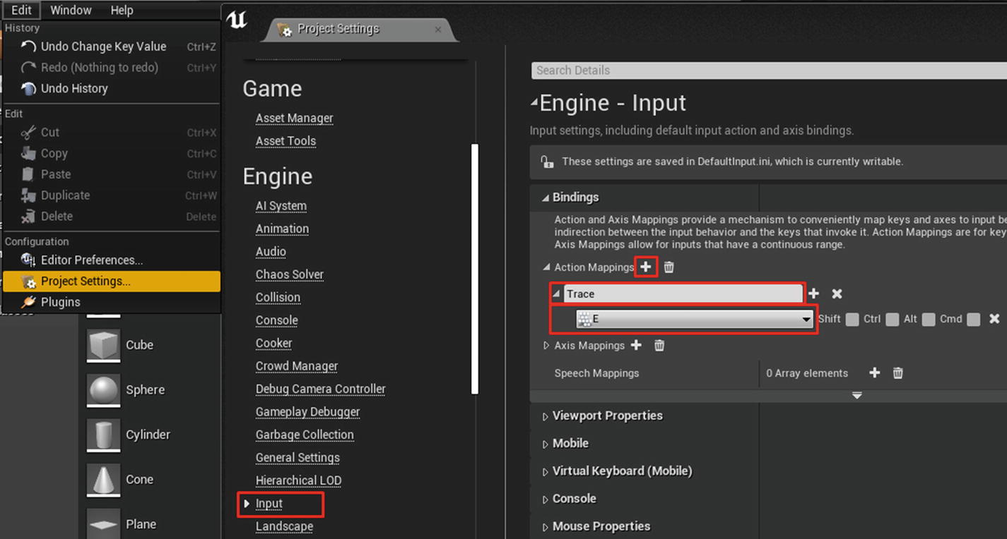
You have now finished the item setup, but what about trace? You do it in the Character class, but you need to have an input to start the trace. To do that, click Edit on the menu bar and select Project Settings. Next, select Input under the Engine section. On the right, click the + button next to Action Mapping. Name the input anything you want, and select a key for it. I named it Trace and chose E for the key (see Figure 5-11).
If you have not added a third-person project, you can do so by clicking the green Add New button in the Content Browser. Select either Add Feature or Content Pack. In the dialog, select Third Person and click +Add to Project.Next, press Shift+Alt+O to open the Open Asset dialog. Search for ThirdPersonCharacter and open it. Alternatively, you can navigate to Content/ThirdPerson/Blueprints and open ThirdPersonCharacter Blueprint (see Figure 5-12).

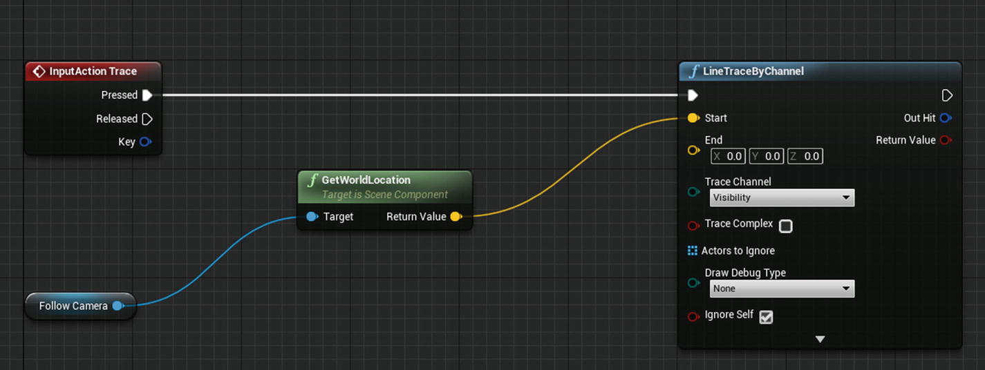
In the Event graph, right-click and search for Input Trace (it is under Input → Action Events). You can add the Trace event, which is invoked when you press the E key. Right-click again on the graph and search for Line Trace By Channel. (There are other types of traces as well, like Box, Capsule, and Sphere. Read more about them at https://docs.unrealengine.com/en-US/Engine/Physics/Tracing/Overview/index.html).
Line Trace By Channel is the primary node that does the tracing from the start location to the end location. Figure 5-4 illustrates where the trace starts from the Camera and shoots to the direction the Camera is facing. To create that setup, right-click the graph and search for GetFollowCamera (no spaces) and select the Get Follow Camera node. This is the getter node for the Camera included with the character in Components. (Alternatively, you can drag the Follow Camera from the Components tab onto the graph to create the node).From the output pin of this node, drag a wire, search for GetWorldLocation, and select it. This node shows the Camera component’s location in the world space. Connect the GetWorldLocation yellow output to the Start input of Line trace node (see Figure 5-13).
Post Link: 5. Physics and Raycasting-1